Modular Containerized Power Plant
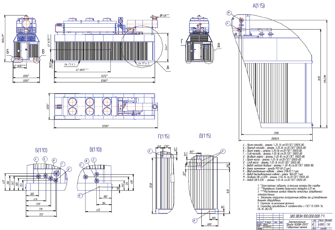
POWER PLANT OUTLINE DRAWING
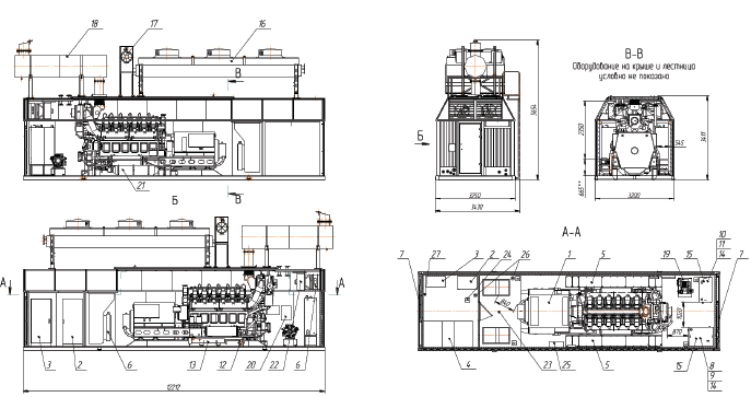
POWER PLANT GENERAL DRAWING
DPS INNER HIGH-VOLTAGE DEVICE
ELECTRIC CIRCUIT

Notes
-
Switchgear is provided with a set of operational blockings with application of electromagnetic locks.
-
Arrangement of power of warning, heating, AUSC cells lightning circuit as well as power by guaranteed control current is executed by the Customer.
-
Single-line diagram is displayed on the side of cells frontage.
-
Cell No.3 is equipped with vacuum circuit breaker with remote switching and block Sirius.
-
Cell No.3 or constructively another cell shall be provided with electricity counter.
-
Auxiliary power transformer capacity is 63 kVA.
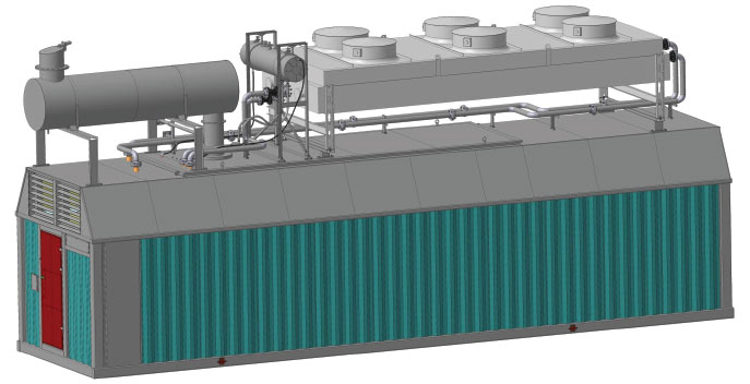
POWER PLANT PHYSICAL CONFIGURATION
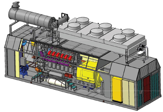
POWER PLANT FACILITIES ARRANGEMENT
MANUFACTURER’S WARRANTY
Correspondence of parameters and specifications of power plant to requirements of the present technical proposal;
Power plant reliable trouble-free operation subject to compliance with conditions and rules of transportation and storage, conservation and depreservation, assembling and operation prescribed for by the present technical solution, power plant operation manual and operational documentation for component parts;
Free of charge elimination of faults and failures as well as replacement of parts and assembly units broken within warranty period or guarantee life due to breakage or early wear consequent to application of poor-quality materials or substandard production.
Warranty period to the power plant makes 12 months since putting into operation and not less than 18 months since shipping;
Warranty to purchased component parts is established by state standards or their specifications;
Upon warranty periods expiration but within the limits of assigned recourse, the manufacture reserves responsibility over quality of power plant facilities.
Supply of new parts and assembly units required to recover power plant working capacity is implemented by the manufacture at the expense of the customer under particular contract.
SAFETY AND ENVIRONMENTAL REQUIREMENTS
All metal parts of electrical facilities that can be under pressure due to isolation failure have electrical connection to the container.
For this purpose, expanding screws are provided for grounding connection as well as grounding signs. External grounding circuit is installed by the Customer in accordance with the power plant location project.
Power plant protection class rating is not less IP23.
The power plant and its main parts design provides protection of operating personnel from electric shock, injuries by rotating and flexible parts and from burn injuries form parts heated up to high temperature. Surface temperature that allows personnel touching during power plant maintenance shall not exceed ЗЗЗК (60°С).
The power plant stands three phase short circuit under protection in any load modes from 0 до 100% free of damage.
ELECTRICAL FACILITIES
(built-in distribution cells)
Power plant is equipped with in-built high-voltage cells with:
a
high-voltage vacuum circuit breaker with voltage measuring transformer
b
cable inlet with voltage measuring transformer
c
auxiliary transformer
Electrical facilities provide commutation of power circuit and switching-off the generator in case circuit failure beyond the breaker; output of measuring voltage in synchronization circuit of the generation set control panel; connection of external power cables of the Customer.
Distribution gear relay protection provides required protection level of all connections. Configuration and specifications of electrical facilities correspond to the item electrical power supply project of the power plant.
Electrical energy technical management counter is installed on the generator control panel.
The power plant is equipped with microprocessor
control system and enables:

-
– operation in single, driven and driving modes;
-
– control over all power plant systems on stand-by to launch and notification on failures prohibiting start;
-
– heat medium automated temperature maintenance in stand-by to launch status in cold season;
-
– automated start and hook up into electrical network in case of circuit voltage loss and the plant shut down during its restoring (emergency energy source);
-
– automated start and hook up into common electrical network of the next power plant in case of their parallel connection subject to generated power shortage or under external command;
-
– automated shut down of the next power plant in case of their parallel connection subject to generated power shortage or under external command;
-
– automated start and shut down (normal and emergency) of prime engine subject to control signal form operator’s room during single operation or from leading power plant subject to parallel connection;
-
– engine rotation frequency automated regulation not lower than third accuracy class index under GOST10511, herewith inclination of regulatory specification in diesel cycle shall be within 0...4%;

-
– preset active and reactive power automated maintenance subject to networking;
-
– automated fuel flow control and generator voltage with compliance to requirements of active and reactive power distribution;
-
– cooling fluid and diesel oil temperature automated regulation both under operation with stand alone cooling and under utilization of process heat (option);
-
– automated emergency shut-down in case of failure preventing further operation;
-
– record and storage of preset parameters in short-term and long-term archives;
-
– capability to connect with of higher order;
The system enables dignified operational efficiency subject to minimum number of operating personnel; stable power plant operation under normal, emergency and post-emergency modes; power plant remote control, engines operation with capabilities of automated and computer-assisted transition from one fuel type to another.
The power plant is provided with required power circuit, diesel-generator and auxiliary equipment protection
Display of information into the object control system is provided by remote monitoring under digital channel (Ethernet access)
Power plant control system is provided with reservation with decrease of automation scope
SUPPORTING SYSTEM SPECIFICATIONS
PRIMARY MOTOR COOLING SYSTEM is dual-cycle.
Hot circuit cools the motor, cold inflating air and oil. Remote coolant unit with electrically driven ventilator(s) is applied as cooling device. Temperature control is implemented by switching on/off ventilators.
Apart from coolant unit, the system consists of electric-traced cooling liquid tank, manually-operated pump for pumping down/off liquid, expansion tanks, pipe lines, durites inside the plant and compensators outside the plant.
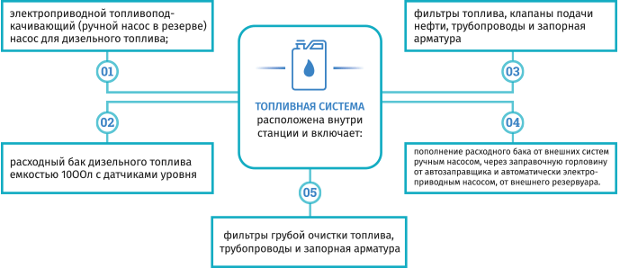
ТОПЛИВНАЯ СИСТЕМА
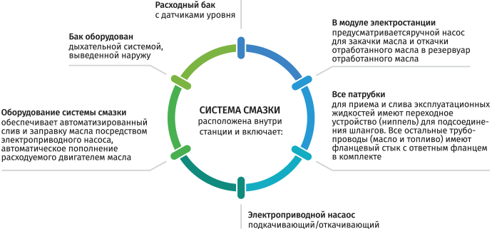
СИСТЕМА СМАЗКИ
AIR SUPPLY AND VENTILATION SYSTEM CONSISTS OF:
Motor air filter
Electrically-driven ventilators
Temperature controllers
Diesel generator set module is provided with supply-extract air-handling unit. Intake and exhaust opening are equipped with noise dampers
Air inlets and outlets with grids, shields and sound absorbent lining
Air valves with electric drive and и electric heating for climatic protection
lighting SYSTEM
-
Containerized power plant is provided with working, emergency, maintenance and external one. Each entrance door is
equipped with external lamp with LED lamp
-
Power plant premises working lighting services with voltage of 220V is implemented form the power plant local distribution board.
-
Emergency lighting is 12 V generated by accumulator batteries.
-
Power plant lighting corresponds to lighting standsrds and makes min:
- - 100 lux – in control places,
- - 50 lux – in maintenance places,
- - 10 lux – floor.
-
Maintenance lighting is portable maintenance lamp to socket of 24V. Lighting of panels and boards in power plant cells where permanent personnel stay is not required, makes at least 20 lux.
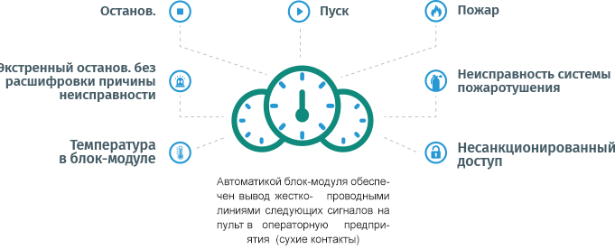
FIRE FIGHTING SYSTEM

DPS block module category of fire and explosion hazard is B. DPS block module premises are subject to automated aerosol firefighting equipment installation (AFFE).
AFFE performs the functions of fire alarm (FA) and fire warning system (WAS). To control unauthorized access to the DPS premises there is security alarm (SA).
AFFE, FA,WAS and SA systems signals are displayed to cable input junction box for connection of remote devices in the premises with presence of permanent attending personnel.
DPS premises are provided with emergency firefighting equipment.
EXHAUST SYSTEM
It consists of the muffler, exhaust pipeline.
To compensate extension of exhaust pipeline, it is equipped with compensator consisting of two flanges, cover and bellow representing by steel channeled cylinder
Necessity and height of chimney stack are determined at the power plant design stage basing on constriction region ecological requirements
CONTAINER DESIGN
The power plant container is a noise-attenuating construction and lowers the noise level up to 85 dBA. In the exhaust system a muffler with active sound absorption is installed.
THE POWER PLANT CONTAINER CONSISTS OF:
- full metal welded main lifting body;
- heat insulation of the main lifting body and the bottom in accordance with the maintenance conditions;
- inner lining of the container body: walls are from sandwich panels, floor is from profiled metal sheet;
- process-oriented and installation openings for the main equipment installation, exhaust and ventilation system assembling;
- DG assembling/disassembling is made in the lift-off cover;
- the body is integrated with supporting structures to fasten the motor-generator unit and auxiliary facilities, installation openings, doors, air valves, exhaust gas and air path and external utilities attachment units;
- entrance doors (min. 1900x750 mm in the light) with finishers;
- air valve paths are closed from outside with wings preventing damage to valves during transportation and storage and providing rain and snow protection;
- external cables entry openings with seal units;
- the container floor is made from steel checkered sheet. To discharge spilled liquid and condensate water the floor is provided with a discharge channel with overflows. On the outside the overflows are covered with prone-to-leaking corks;
- bolt clamps for power plant grounding;
- corrosion-resistant protective coating of inner and outer surfaces complies with IV class under GOST 9.032;
- container unit doors are equipped with locking devices (the lock provides door opening from the inside without a key), resilient seals to decrease heat loss and increase particles confinement and moisture resistance;
- the power plant equipment colouring under GOST 14202 excludes operating personnel’s fatigue;
- paint coating thickness of external sheets is at least 80 um. All containers have a single colour range agreed with the Customer;
- the container is divided by the wall with a door into two modules: service and control.
CONTAINER DESIGN:
Fire resistance rating is III.
Structural fire hazard class is СО.
Engineering structure fire hazard class is КО.
Container category under explosion-fire and fire hazard is В.
Functional fire hazard class is F5.1
Container construction and capability enables power plant transportation by water (sea and river) transport, by road and rail.
Container is equipped with special devices providing firm fastening to load-carrying devices. The design enables firm attachment during transportation.
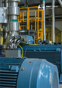
ENGINE GENERATOR MODULE
-
System of air delivery,
ventilation and heating
-
Lighting system
-
Firefighting system
-
Management system
-
Switching
electrical
facilities
-
Microprocessor operation
panel
-
Power generating set
-
Fuel supply system
-
Oil supply system
-
Cooling system
-
Exhaust system
-
Starting systemа
SPECIFICATIONS OF ENGINE GENERATOR
SPECIFICATIONS OF THE POWER PLANT
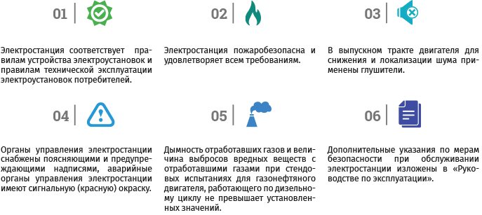
FACTS ABOUT THE POWER PLANT
01
Under no-load conditions the power plant provides the possibility to launch non-loaded asynchronous short-circuited motor with a capacity not exceeding 30% of the nominal capacity of the power plant and with in-rush starting current with frequency up to 7 of nominal value.
02
The power plant is equipped with electric heating devices maintaining the temperature of heat transfer medium under non-working engine-generator within the set limits under ambient air temperature up to minus 60°С with charged systems if external source of power supply is present. Warm-up time, including no load operation of primary motor providing 100% load acceptance is not more than 60 minutes.
03
The power plant is resistant to external mechanical impacts during operation and transportation.
04
The power plant enables assembling and disassembling of power generating set with the use of the crane through the lift-off cover
INTRODUCTION
Proposal for engineering, production, construction, assembling and commissioning works of the power plant is formed on the basis of technical requirement of the Customer and experience
 in construction of counterpart power plants in different regions of the Russian Federation. The power plant is designated for electric power supply to the Customer’s consumers.
The fuel for the power plant is crude oil (applicability of the fuel shall be agreed by the Customer with the engine manufacture). Power plant operation is basic in autonomous mode. Technical solutions can be changed and amended at the stage of design and engineering documentation execution.
The present technical proposal is designed for information and determination of the preliminary price for the services rendered to the Customer and cannot be presented as a specification or as a part of the design documentation.
ATTRIBUTES OF THE MAIN TECHNICAL SOLUTIONS PROPOSED
Two containerized power plants are used as main equipment.
Replenishment of the supply tank with diesel fuel is implemented by standard electric pump from diesel fuel storage tank under level transmitter alarms.
To prevent carbonizing of the turbine wheelspace of the turbocompressor by incomplete combustion products of fuel the engine generator is equipped with turbine wash device. The wash is implemented by the water prepared in the 1 time per 50 hours of work (if there is a boiler-house, chemically prepared water is admitted).
The starting system of engine-generators is pneumatic cylinder. Each engine is equipped with starting compressor and two compressed-air bottles with automated pressure maintenance in the bottle providing at least 6 starts as well as wash of the turbine of the turbocompressor and blowing of the automatically cleaned filter.
Diesel fuel is used as pilot oil upon start and shut down.
Management of power plant engine-generator, auxiliary engineering systems and facilities is implemented by its automated control system (ACS) and automated process control system (APCS).
APCS of the power plant provides power plant management: start, shut down, operation mode, automated and manual transition from one type of fuel to another and etc., as well as control over operation of separate systems of power.
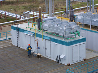
In terms of design, the power plant is containerized that allows implementing assembling and commissioning works of the main equipment under the factory environment.
This reduces the time limits for construction of the plant and provides high quality supported by quality system ISO 9001. The main manufacturing equipment and systems, apart from coolant unit and exhaust pipe with damper are placed in tanks
THE CUSTOMER PROVIDES TANK BATTERY AS WELL AS:
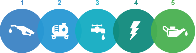
Supply of
generated
fuel
Supply of
diesel
fuel
Supply of
water for
distillatory auxiliaries
Power supply of plant auxiliaries by alternating current and voltage 380/220 standby
Provision of necessary oil and antifreeze supply
THE POWER PLANT CONSISTS OF THE FOLLOWING
MAIN EQUIPMENT
A unit of main manufacturing equipment
including containerized power plant
completed with all necessary equipment
providing start, uninterrupted operation and
power output to the Customer’s consumers
Automated process control system
of the power plant
A suit of assembling parts
A package of maintenance documentation in the
Russian language